Allows precise synchronization (< 10µs) across multiple camera sensors and potentially with other hardware, e.g. flash LED, external IMU, or other cameras.
FSYNC signal
FSYNC/FSIN (frame sync) signal is a pulse that is driven high at the start of each frame capture. Its length is not proportional to the exposure time. It can be either input or output. It operates in 1.8V logic.On stereo cameras (OAK-D*), we want stereo camera pair (monochrome cameras) to be perfectly in sync, so one camera sensor (eg. left) has FSYNC set to INPUT, while the other camera sensor (eg. right) has FSYNC set to OUTPUT. In such configuration the right camera drives left camera.
FSYNC signal output
At the moment, only OV9282/OV9782 can output FSYNC signal, while IMX378/477/577/etc should also have the capability, but isn't yet supported (so these can not drive FSYNC signal, only be driven by it). AR0234 has input-only FSYNC trigger.
Synchronizing frames externally
If we would like to drive cameras with an outside signal, we would need to set FSIN as INPUT for camera sensors.All Series 2 OAK PoE models have an M8 I/O connector which exposes FSIN signal (and also STROBE). We have developed FSYNC Y-Adapter that allows you to sync (daisy-chain) multiple OAK cameras together.
Py
1# Example: we have 3 cameras on ports A,B, and C2cam_A.initialControl.setFrameSyncMode(dai.CameraControl.FrameSyncMode.INPUT)3cam_B.initialControl.setFrameSyncMode(dai.CameraControl.FrameSyncMode.INPUT)4cam_C.initialControl.setFrameSyncMode(dai.CameraControl.FrameSyncMode.INPUT)
You can also control FSIN line via GPIO from within Script, see example here.
Sensor FSYNC support
As noted above the paragraph, only some sensors support FSYNC syncing. There are 2 types of FSYNC syncing:
Continuous streaming with external syncing, configured with CameraControl.setFrameSyncMode(). In this mode, the FSIN signal is expected to arrive at a continuous rate matching the configured sensor FPS, and trigger can't arrive at arbitrary times as that would disrupt internal sensor operations (leading to bad frames, etc). It can only correct for very small amounts of drift over time.
Snapshot mode with external syncing, configured with CameraControl.setExternalTrigger(). In this mode, trigger can arrive to the sensor at any time, and the sensor will take the photo/snapshot.
Arbitrary external trigger supported on XTR/XTRIG pin. Pulse length determines exposure time (sensor feature). Global Arbitrary external trigger supported on XTR/XTRIG pin. Pulse length determines exposure time (sensor feature).
External FSYNC Example
Older devices
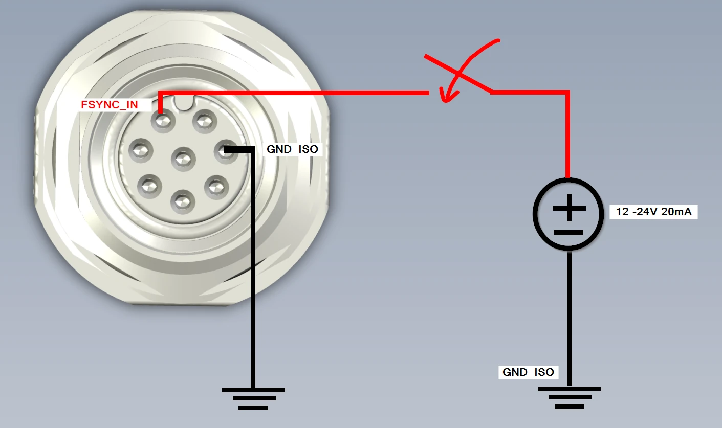
Here's an example of how to use external FSYNC signal to trigger camera sensors. You can use any Series 2 OAK-D PoE model to trigger the FSYNC. We used M8 breakout board to expose the GND/FSYNC lines.
In this example (script here), sensors were set to Snapshot mode, as we were triggering the signal with a switch button. Only stereo cameras (2x OV9282) were triggered by the button, as IMX378 color camera does not support snapshot mode. If we were to use OV9782 color camera, it could be triggered by the button as well.
Newer devices
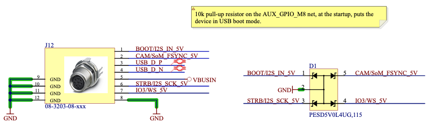
Devices that use the new M8 connector (like the OAK-D ToF) will expect a 5V trigger signal.By default, pin 2 on the M8 connector (FSYNC) is pulled high internally. When the pin is pulled high, it will stream frames continuously (when camera is either in INPUT or OUTPUT mode). To trigger frames externally, you will need to pull the pin low (eg. to pin 8 - GND) to stop the frame streaming, then pull it high again to start streaming.This way you can send 5V pulses to the FSYNC pin to trigger the frame capture.
FSYNC Triggering
Only global shutter (OV9282, OV9782, AR0234...) cameras support FSYNC triggering in photo/snapshot mode. Rolling shutter cameras (IMX378, IMX477, IMX577, etc) don't support it.
Strobe signal
STROBE signal is an output from the image sensor, and is active (high) during the exposure of the image sensor. It would be used to eg. drive an external LED lighting for illumination - so lighting would only be active during exposure times, instead constantly on, which would decrease power consumption and heating of the lighting.We have used STROBE signal on Pro version of OAK cameras (which have on-board illumination IR LED and IR laser dot projector) to drive the laser/LED.
Strobe demo
Cameras with M8 connector allow you to connect external lighting to the STROBE signal, as demonstrated in the video below (blog post here):
Frame capture graphs
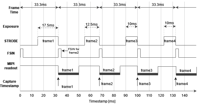
Frame timestamp is assigned to the frame at the MIPI SoF (start of frame) event, when the sensor starts streaming the frame (MIPI readout).For global shutter sensors, this follows immediately after the exposure for the whole frame was finished, so we can say the timestamp assigned is aligned with end of exposure-window (within a margin of few microseconds). Here's an example graph of the global shutter sensor timings, which demonstrates when timestamp is assigned to the frame:
Global shutter sensor timings
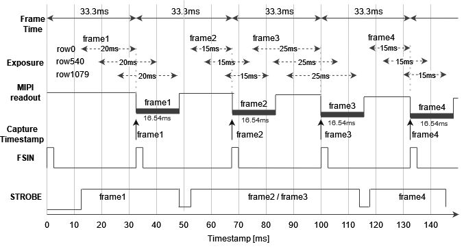
For rolling shutter, the example graph looks a bit different. MIPI SoF follows after the first row of the image was fully exposed and it's being streamed, but the following rows are still exposing or may have not started exposing yet (depending on exposure time).
Rolling shutter sensor timings
Below there's an example graph of rolling shutter sensor (IMX378) at 1080p and 30fps (33.3ms frame time). MIPI readout time varies between sensors/resolutions, but for IMX378 it's 16.54ms at 1080P, 23.58ms at 4K, and 33.04ms at 12MP.
OAK-FFC hardware syncing
On OAK-FFC-4P, we have 4 camera ports; A (rgb), B (left), C (right), and D (cam_d). A & D are 4-lane MIPI, and B & C are 2-lane MIPI. Each pair (A&D and B&C) share an I2C bus, and the B&C bus is configured for HW syncing left+right cameras by default.For A&D ports, you need to explicitly enable hardware syncing:
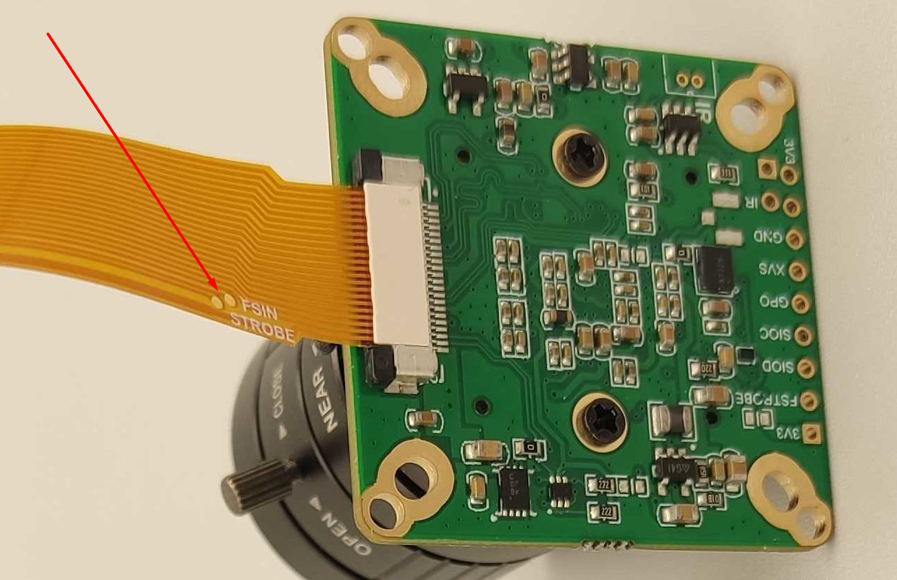
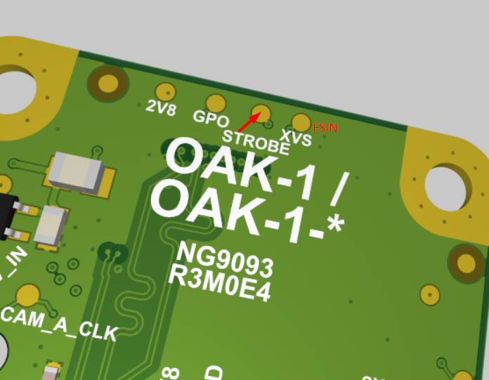
Arducam FFC cameras have a 22-pin connector, which don't have lines for FSIN/STROBE. As seen below, to connect Arducam FFC camera to our OAK-FFC baseboard you need to use 26-to-22 pin converter connector which only exposes STROBE/FSIN lines via test pads. To sync these cameras, you could either solder a wire from test pad to the camera module's FSIN header pin, or connect all FSIN header pins together, as done here.
Connecting FSIN/STROBE
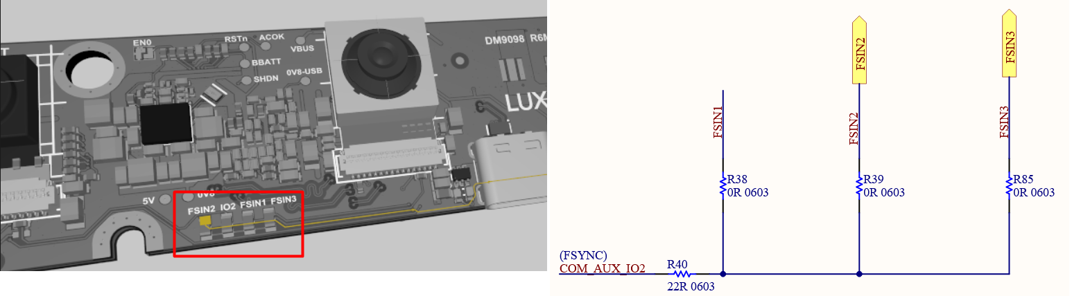
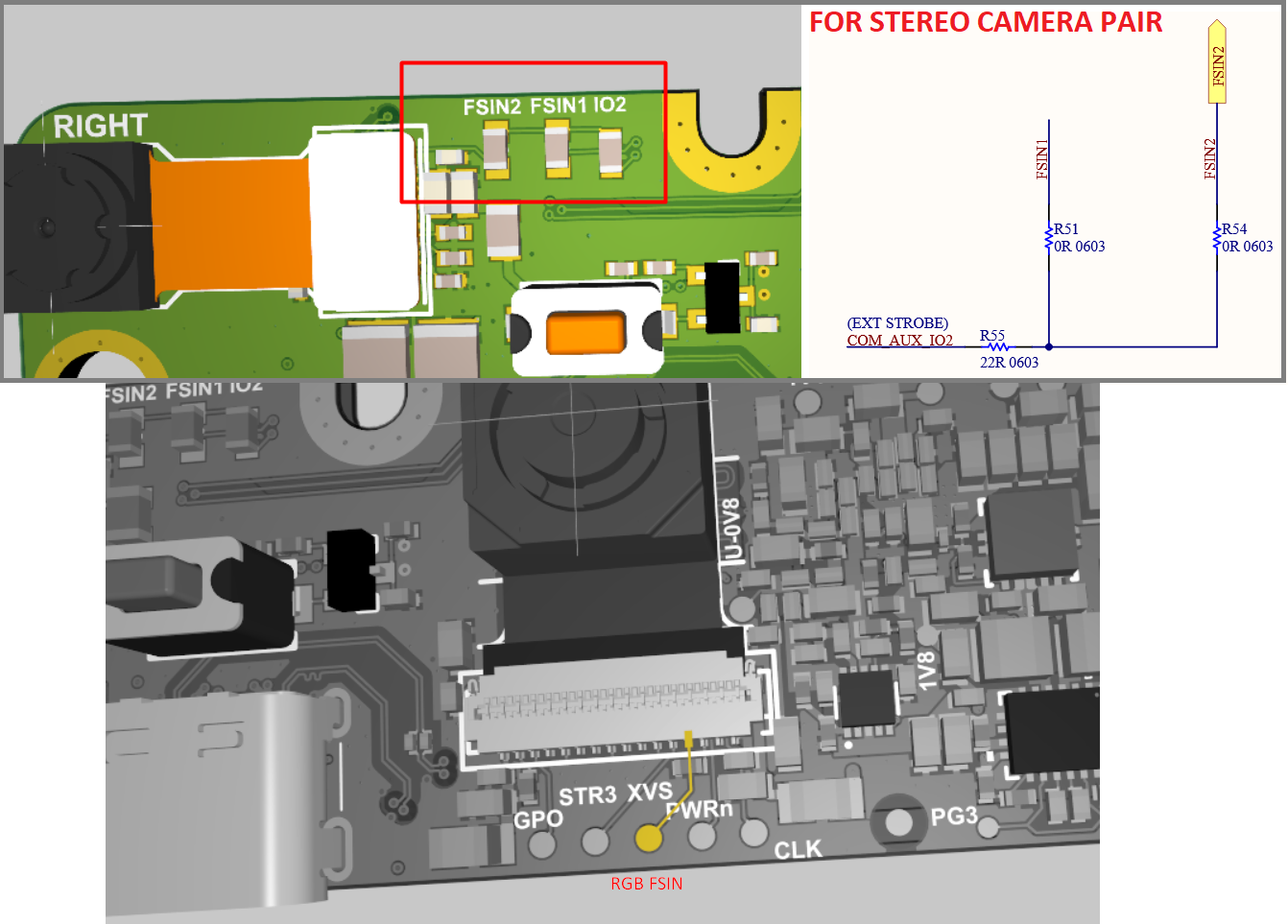
As mentioned, all Series 2 OAK PoE models have an M8 I/O connector with FSYNC/STROBE signal. But if you won't be using these, you will likely need to solder a wire to the PCB on your device. Most PCB designs are open-source (on oak-hardware repository), so you can easily check where FSIN/STROBE signals are on the PCB.
OAK-FFC-4P FSIN
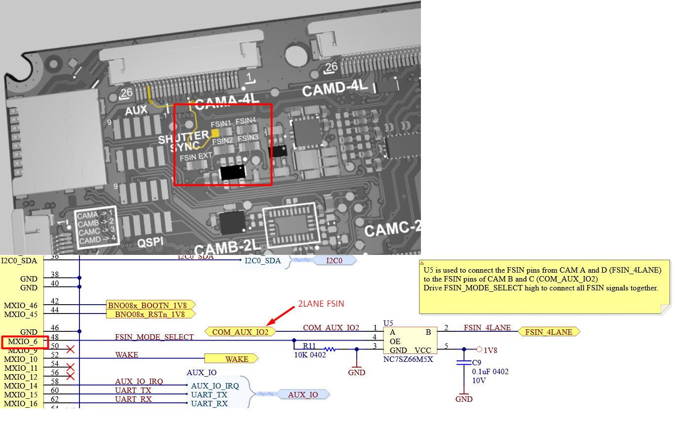
As shown on image above, on OAK-FFC-4P you can enable connection of FSIN_4LANE and FSIN_2LANE with the MXIO6. The script below will sync together all 4 cameras that are connected to the OAK-FFC-4P.
Python
1# CAM_A will drive FSIN signal for all other cameras:2cam_A.initialControl.setFrameSyncMode(dai.CameraControl.FrameSyncMode.INPUT)# 4LANE3cam_B.initialControl.setFrameSyncMode(dai.CameraControl.FrameSyncMode.OUTPUT)# 2LANE4cam_C.initialControl.setFrameSyncMode(dai.CameraControl.FrameSyncMode.INPUT)# 2LANE5cam_D.initialControl.setFrameSyncMode(dai.CameraControl.FrameSyncMode.INPUT)# 4LANE67# AND importantly to tie the FSIN signals of A+D and B+C pairs, by setting a GPIO:8# OAK-FFC-4P requires driving MXIO6 high (FSIN_MODE_SELECT) to connect together9# the A+D FSIN group (4-lane pair) with the B+C group (2-lane pair)10config = dai.Device.Config()11config.board.gpio[6]= dai.BoardConfig.GPIO(dai.BoardConfig.GPIO.OUTPUT,12 dai.BoardConfig.GPIO.Level.HIGH)1314with dai.Device(config)as device:15 device.startPipeline(pipeline)
CAM_B and CAM_C (2-lane MIPI ports) share the same I2C bus, which means if both of them have the same sensor (FFC module) connected to them, they will be in sync regardless of any setting (as I2C command "start exporute" will arrive at the same time).This mechanism is used accross OAK-D cameras to sync stereo camera pair.