FFC 部署指南
OAK-FFC 4P 和 OAK-FFC 4P PoE 硬件更新
2026年5月之后生产的设备将不包含eMMC存储。需要eMMC?请联系我们的支持团队 support@luxonis.com。
概述
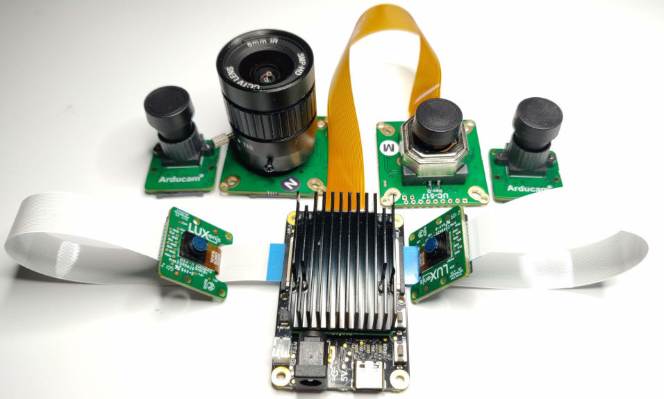
OAK FFC 底板
FFC 摄像头模块
| OAK FFC 摄像头模块 | 快门 | 分辨率 | 备注 |
|---|---|---|---|
| OAK-FFC-IMX378 (AF) | 卷帘 | 12MP | 彩色,自动对焦 |
| OAK-FFC-IMX378-FF | 卷帘 | 12MP | 彩色,定焦 |
| OAK-FFC-IMX378-W | 卷帘 | 12MP | 彩色,定焦,宽视场角 |
| OAK-FFC-OV9282 | 全局 | 1MP | 黑白,定焦 |
| OAK-FFC-OV9282-M12 | 全局 | 1MP | 黑白,M12接口 |
| OAK-FFC-OV9282-W | 全局 | 1MP | 黑白,定焦,宽视场角 |
| OAK-FFC-OV9782-M12 | 全局 | 1MP | 彩色,M12接口 |
| OAK-FFC-OV9782-W | 全局 | 1MP | 彩色,定焦,宽视场角 |
| OAK-FFC IMX582 | 卷帘 | 32MP | 彩色,自动对焦 |
| OAK-FFC-IMX577-M12 | 卷帘 | 12MP | 彩色,M12接口 |
| OAK-FFC-IMX214-W | 卷帘 | 13MP | 彩色,定焦,宽视场角 |
| OAK-FFC-AR0234-M12 | 全局 | 2.3MP | 彩色,M12接口 |
| OAK-FFC-IMX462 (M12) | 卷帘 | 2MP | 彩色,定焦 |
| Arducam HQ Cam for RPi, IMX477 | 卷帘 | 12.3MP | 彩色,CS接口镜头 |
Raspberry Pi 摄像头模块
| RPi 摄像头模块 | 传感器 | 快门 | 像素 | 备注 |
|---|---|---|---|---|
| RPi Camera Module 3 | IMX708 | 卷帘 | 12 MP | 彩色,自动对焦。初始(WIP)集成 |
| RPi Camera Module 2 | IMX219 | 卷帘 | 8 MP | 彩色,定焦。需要 imx219 分支 |
| RPi High Quality Camera | IMX477 | 卷帘 | 12 MP | 彩色,C/CS接口 |
| RPi Global Shutter Camera | IMX296 | 全局 | 1.6 MP | 彩色,C/CS接口。可能存在颜色伪影,见解决方案 |
UC-244 适配器与 RPi HQ 和全局快门摄像头不兼容。需要额外步骤,详见此处。
FFC 摄像头安装
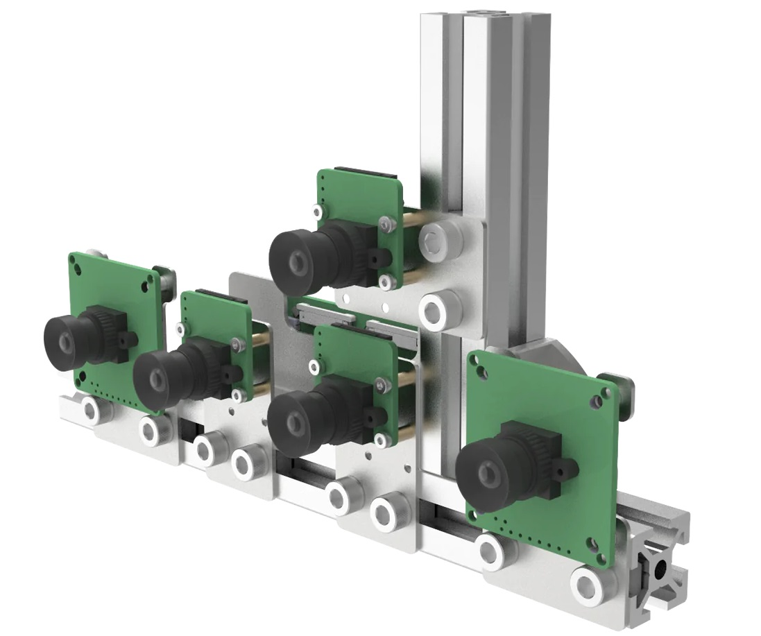
M12 安装镜头
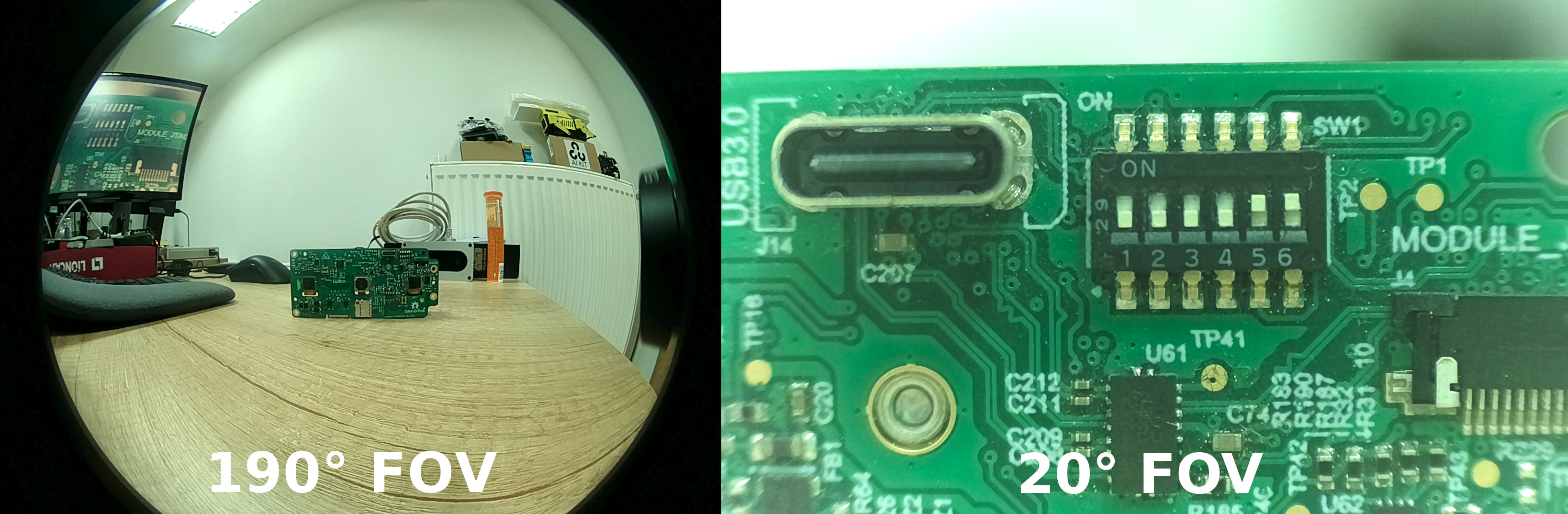
M12 可选择的视场角
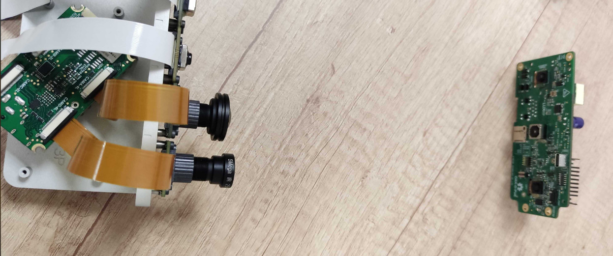
俯视图测试设置
使用 OAK FFC 进行开发
将摄像头连接到基板后,您可以使用 utilities/cam_test.py 脚本快速测试摄像头是否正常工作。默认情况下,它会尝试在 2 通道 MIPI 端口 B(左)和 C(右)上运行 2 个单目摄像头,并在端口 A(RGB)和 D(4 通道 MIPI 端口)上运行 2 个彩色摄像头。如果您连接了不同的摄像头,可以通过 例如,如果您在端口 A、B 和 C 上连接了 3 个单目摄像头,可以运行以下命令:
--cameras 参数指定要使用的摄像头类型:Command Line
1cam_test.py [-h] [--cameras <BoardSocket>,<CameraType>]Command Line
1python3 cam_test.py --cameras rgb,m right,m left,m类似地,要将此类配置添加到脚本中,可以使用以下代码:
Python
Python
1cam_a = pipeline.create(dai.node.Camera)
2cam_a.build(dai.CameraBoardSocket.CAM_A) # 等同于 CameraBoardSocket.RGB
3
4cam_b = pipeline.create(dai.node.Camera)
5cam_b.build(dai.CameraBoardSocket.CAM_B) # 等同于 CameraBoardSocket.LEFT
6
7cam_c = pipeline.create(dai.node.Camera)
8cam_c.build(dai.CameraBoardSocket.CAM_C) # 等同于 CameraBoardSocket.RIGHT
9
10cam_d = pipeline.create(dai.node.Camera)
11cam_d.build(dai.CameraBoardSocket.CAM_D)Extending functionality
PSRBS Connector
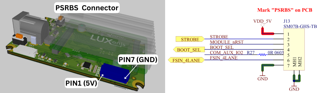
| Pin | Name | Description |
|---|---|---|
| 1 | VDD_5V | 5V power input/output |
| 2 | STROBE | Strobe signal output, can drive external lighting (projector, illumination lights, etc.) |
| 3 | MODULE_nRST | Allows resetting the OAK-FFC from an external source (GND will reset the RVC2, same as RST button) |
| 4 | BOOT_SEL | Allows selecting whether to boot into the bootloader (1.8V will skip bootloader, same as BOOT button) |
| 5 | COM_AUX_IO2 | 2-lane MIPI FSYNC signal input/output |
| 6 | FSIN_4LANE | 4-lane MIPI FSYNC signal input/output |
| 7 | GND | GND power input/output |
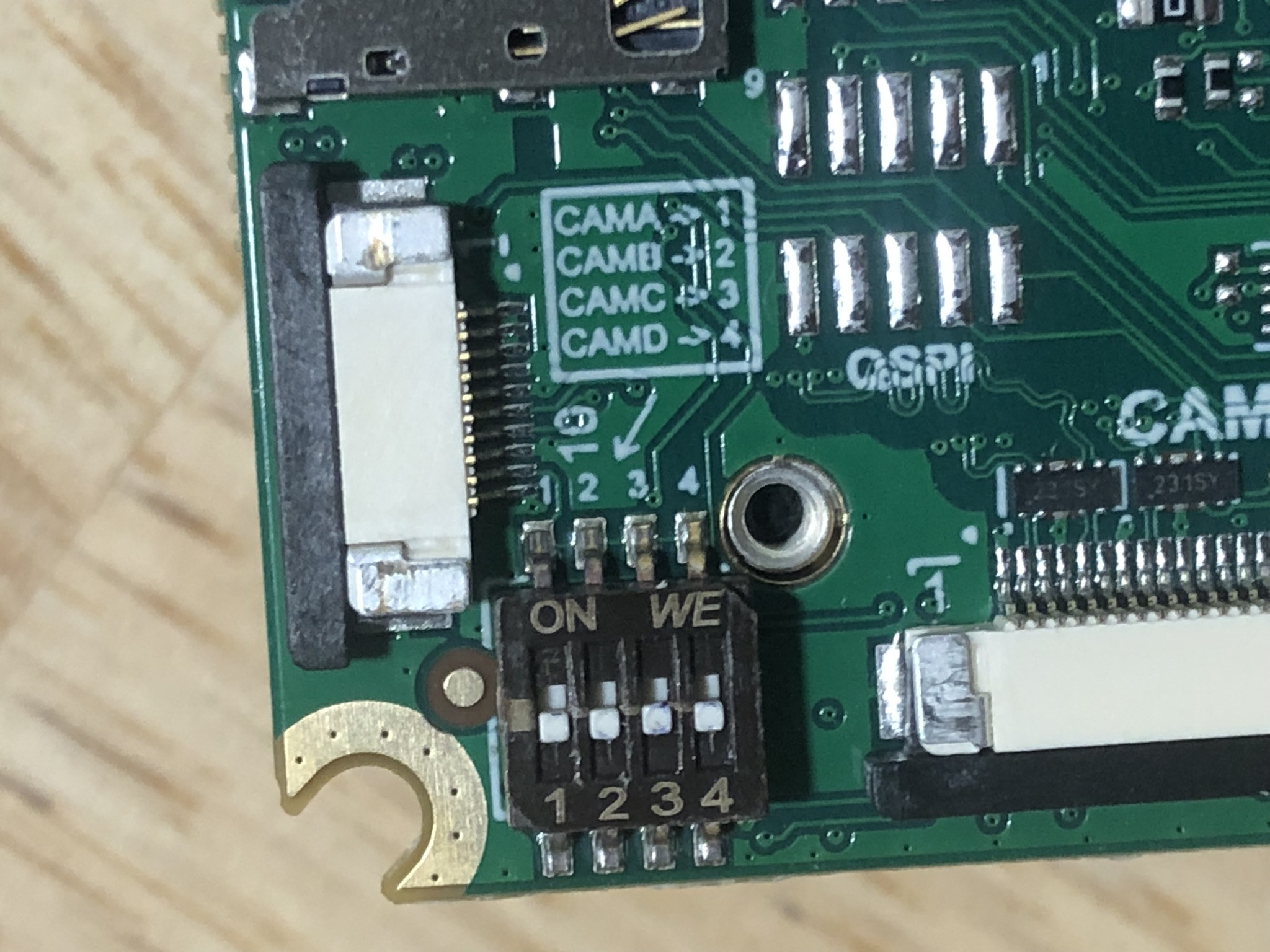
Connecting an IR Module
UART
UART Pinout
| OAK-FFC Device | TX | RX |
|---|---|---|
| OAK-FFC-4P | 15 | 16 |
| OAK-FFC-4P POE | / | / |
| OAK-FFC-1P POE | 45 | 46 |
| OAK-FFC-3P | / | / |
SD Card support
需要帮助?
请前往 OAKChina 官网 获取技术支持或解答您的任何疑问。