此页面由 AI 自动翻译。查看英文原版
最后更新

本页目录

  • 如何放置
  • 输入和输出
  • ToF 配置文件
  • 架构和输出
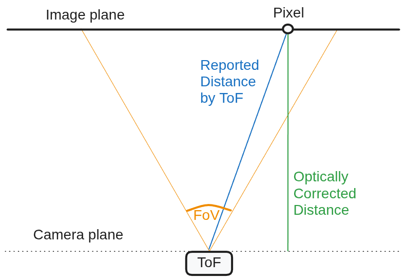
  • 输出去畸变 (RVC4)
  • 用法
  • 示例
  • 参考
Claude CodeCodexCursor
Luxonis 智能体工具包为你常用的编程智能体加载 Luxonis 上下文与技能,更快地基于 OAK 开发应用。
安装工具包
最后更新
Supported on:RVC2RVC4
ToF 节点将原始飞行时间传感器数据转换为深度,并公开基本输出和过滤输出。它适用于集成 ToF 传感器的 RVC2 和 RVC4 设备,例如:ToF 深度可以直接与空间节点一起使用,例如 SpatialDetectionNetwork 和 SpatialLocationCalculator。有关与立体声深度质量比较,请参阅 ToF 深度精度。

如何放置

Python

Python
1pipeline = dai.Pipeline()
2tof = pipeline.create(dai.node.ToF)

C++

C++
1dai::Pipeline pipeline;
2auto tof = pipeline.create<dai::node::ToF>();

输入和输出

  • rawDepth 和 phase 是仅限 RVC2 的输出。
  • raw 和 confidence 是仅限 RVC4 的输出。

ToF 配置文件

配置 ToF 节点的推荐方法是通过 配置文件。配置文件为给定操作范围设置默认值,而无需手动调整低级参数。配置文件在 RVC2 和 RVC4 上是统一的。
配置文件大致范围典型用例
LOW_RANGE~10 厘米到 1.5 米短距离应用,例如料箱拣选
MID_RANGE (默认)~10 厘米到 5 米通用配置文件
HIGH_RANGE从 ~3 米及更远长距离感应

Python

Python
1pipeline = dai.Pipeline()
2
3tof = pipeline.create(dai.node.ToF)
4tof.build(
5    boardSocket=dai.CameraBoardSocket.AUTO,
6    profile=dai.ToFConfig.Profile.MID_RANGE,
7    fps=FPS,
8)

C++

C++
1dai::Pipeline pipeline;
2
3auto tof = pipeline.create<dai::node::ToF>()->build(
4    dai::CameraBoardSocket::AUTO,
5    dai::ToFConfig::Profile::MID_RANGE
6);

架构和输出

RVC2

在 RVC2 上,depth 输出由 ImageFilters 节点在主机上过滤。RVC2 配置文件将主机端过滤器预设与内部 ToF 设置相结合。输出为:
  • depth (uint16, mm)
  • amplitude (uint16)
  • intensity (uint8)
  • rawDepth (uint16, mm)
  • phase (float32)

RVC2 ToF 设置

常见的基本解码设置(来自 ToFConfig):
  • 相位解缠绕:以增加噪声为代价扩展范围。
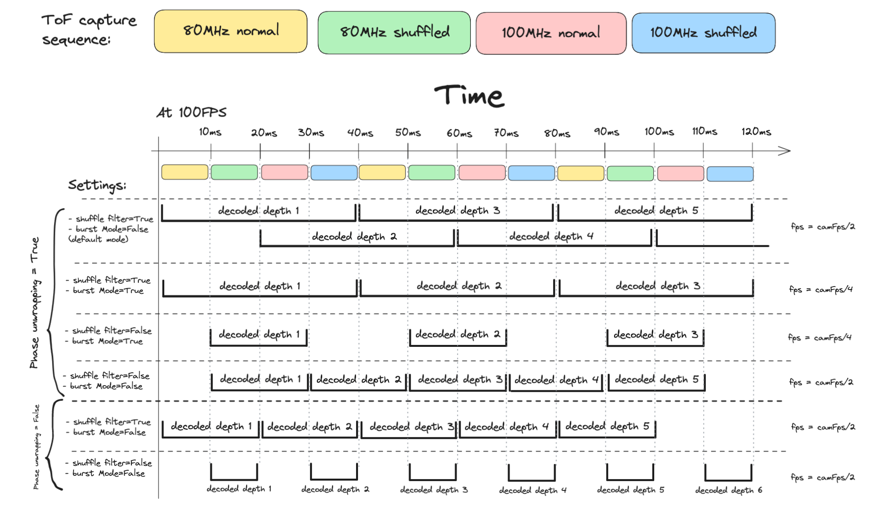
  • 相位混洗时间滤波器:通过组合混洗/非混洗捕获来降低噪声。
按解缠绕级别的大致范围:
  • 0(禁用):高达 ~1.87 米(80 MHz)
  • 1:高达 ~3.0 米
  • 2:高达 ~4.5 米
  • 3:高达 ~6.0 米
  • 4:高达 ~7.5 米

RVC2 深度图像滤波器

后处理通过 ImageFilters 和 ImageFiltersConfig 进行配置。对于置信度驱动的清理,请参阅 ToFDepthConfidenceFilterConfig。由于这些滤波器在主机上运行,如果处理或带宽是瓶颈,请考虑禁用它们。有关性能影响的深入了解,请参阅 这篇博客文章。 要禁用所有主机端滤波器:
Python
1filters_cfg = dai.ImageFiltersConfig()
2filters_cfg.insertFilter(dai.node.ImageFilters.MedianFilterParams.MEDIAN_OFF)
3
4temporal = dai.node.ImageFilters.TemporalFilterParams()
5temporal.enable = False
6filters_cfg.insertFilter(temporal)
7
8speckle = dai.node.ImageFilters.SpeckleFilterParams()
9speckle.enable = False
10filters_cfg.insertFilter(speckle)
11
12spatial = dai.node.ImageFilters.SpatialFilterParams()
13spatial.enable = False
14filters_cfg.insertFilter(spatial)
15
16filters_cfg_q.send(filters_cfg)

快速调优指南

调优目标是平衡干净、无噪声的深度图与移动物体的快速、准确更新。 对于 ToF 深度输出,delta 通常解释为深度单位(通常是毫米),而 alpha 是 [0.0, 1.0] 中的混合因子。 将以下所有值视为起点,并根据您的场景进行调优。
步骤 1:空白状态
在调优之前,禁用所有滤波器。 这有助于您测量基线噪声,验证传感器放置/照明,并避免用软件滤波掩盖设置问题。
步骤 2:时间滤波器(从这里开始)
首先调优 TemporalFilterParams,因为它控制随时间的动态平滑。
  • delta:用于判断深度变化是显著变化还是噪声的阈值。
    • 从 delta = 15 开始。
    • 对于较大的物体(例如约 50 毫米的物体高度),使用 delta = 25 以便运动快速更新。
    • 对于小物体,收紧到 delta = 10。
  • alpha:当前帧与历史记录的混合权重。
    • 较低的 alpha(例如 0.1)提供更平滑的输出,但可能引入延迟/拖影。
    • 较高的 alpha(例如 0.4)更新更快,但平滑度较低。
  • 重要:delta = 0 使几乎所有变化都显著,并且在很大程度上绕过了时间混合。
步骤 3:斑点滤波器
使用 SpeckleFilterParams 移除单个帧中的孤立斑点和椒盐状伪影。
  • differenceThreshold:将相邻像素分组到同一区域的阈值。
  • speckleRange:要移除的最大区域大小。
  • 调优策略:逐渐增加 speckleRange 以移除较大的浮动斑点,但避免删除真实小物体的数值。
步骤 4:空间滤波器
使用 SpatialFilterParams 平滑物体表面,同时保留边缘。
  • alpha:平滑强度(较低的值通常平滑度更高)。
  • delta:边缘保留阈值;较大的深度跳变被视为边缘,不进行混合。
  • holeFillingRadius:从周围有效数据填充无效 (0) 像素。
  • numIterations:更多遍数可以以轻微的处理成本细化输出。
步骤 5:中值滤波器
当残留椒盐噪声仍然存在时,使用 MedianFilterParams 进行最终的激进清理。
  • 此节点中支持的模式:MEDIAN_OFF、KERNEL_3x3、KERNEL_5x5。
  • 使用解决噪声的最小内核,以最大程度地减少边缘/细节损失。

调优快速参考

滤波器关键参数主要用例权衡
时间delta、alpha随时间平滑动态噪声平滑度与运动滞后
斑点speckleRange、differenceThreshold移除孤立斑点/噪声清洁度与删除小物体
空间delta、alpha、holeFillingRadius、numIterations表面平滑与边缘保留平滑度与处理成本
中值KERNEL_3x3、KERNEL_5x5激进的椒盐清理噪声消除与边缘/细节模糊

ToF 运动模糊

为了减少运动模糊:
  • 提高传感器 FPS(高达 160 FPS),同时考虑更高的系统负载和更短的曝光时间。
  • 禁用相位混洗时间滤波器(噪声更高)。
  • 禁用相位解缠绕(降低最大范围)。
  • 在适用时启用突发模式。

最大距离

最大距离取决于调制频率和相位解缠绕设置。
Math
1c = 299792458.0 # 光速(米/秒)
2
3MAX_80MHZ_M = c / (80000000 * 2) = 1.873 米
4MAX_100MHZ_M = c / (100000000 * 2) = 1.498 米
5
6MAX_DIST_80MHZ_M = (phaseUnwrappingLevel + 1) * 1.873 + (phaseUnwrapErrorThreshold / 2)
7MAX_DIST_100MHZ_M = (phaseUnwrappingLevel + 1) * 1.498 + (phaseUnwrapErrorThreshold / 2)

RVC4

ToF 节点在计算深度之前在相位域中执行解码和滤波 在设备上。没有数据传输到主机进行滤波。输出为:
  • depth (uint16, mm)
  • amplitude (uint8, 对数压缩)
  • intensity (uint8, 对数压缩)
  • confidence (uint8, 对数压缩)
  • raw (打包,传感器原生格式)

输出去畸变 (RVC4)

在 RVC4 上,使用 setOutputUndistortion 对 ToF 深度帧进行去畸变。在启动管道之前在 ToF 节点上启用它:

Python

Python
1tof.setOutputUndistortion(True)

C++

C++
1tof->setOutputUndistortion(true);
去畸变后的深度帧可在 depth 输出上获得。

用法

Python

Python
1pipeline = dai.Pipeline()
2
3tof = pipeline.create(dai.node.ToF).build(
4    boardSocket=dai.CameraBoardSocket.AUTO,
5    profile=dai.ToFConfig.Profile.MID_RANGE,
6)
7
8depth_q      = tof.depth.createOutputQueue()
9amplitude_q  = tof.amplitude.createOutputQueue()
10intensity_q  = tof.intensity.createOutputQueue()
11confidence_q = tof.confidence.createOutputQueue()

C++

C++
1dai::Pipeline pipeline;
2
3auto tof = pipeline.create<dai::node::ToF>()->build(
4    dai::CameraBoardSocket::AUTO,
5    dai::ToFConfig::Profile::MID_RANGE
6);
7
8auto depthQ      = tof->depth.createOutputQueue();
9auto amplitudeQ  = tof->amplitude.createOutputQueue();
10auto intensityQ  = tof->intensity.createOutputQueue();
11auto confidenceQ = tof->confidence.createOutputQueue();

示例

参考

class

dai::node::ToF

variable
Subnode< ToFBase > tofBase
variable
Output & rawDepth
Raw depth output from ToF sensor. On RVC2 this is connected to the unfiltered base depth output. On RVC4 this is an unconnected placeholder output.
variable
Output & depth
Filtered depth output
variable
Output & amplitude
Amplitude output
variable
Output & intensity
Intensity output
variable
Output & confidence
Confidence output
variable
Output & phase
Phase output
variable
Output & raw
Raw data coming from the sensor
variable
Input & inputConfig
Runtime ToFConfig input for the ToF base node (decoder on RVC2, IPP on RVC4).RVC4: directly reconfigures the IPP that produces depth. RVC2: reconfigures the decoder that feeds the host ImageFilters. The host-filter stage that actually produces depth is NOT controlled here — to retune the host filters at runtime send an ImageFiltersConfig to imageFiltersInputConfig.
variable
Input & tofBaseInputConfig
Input config for ToF base node
variable
Input * imageFiltersInputConfig
Input config for image filters
variable
ToFBase & tofBaseNode
ToF base node
variable
ImageFilters * imageFiltersNode
Image filters node
inline function
ToF()
function
ToF(const std::shared_ptr< Device > & device)
function
~ToF()
function
void buildInternal()
Function called from within the create function to build the node. This function is useful for initialization, setting up inputs and outputs = stuff that cannot be perform in the constuctor.
function
std::shared_ptr< ToF > build(dai::CameraBoardSocket boardSocket, dai::ImageFiltersPresetMode presetMode, std::optional< float > fps)
Build the ToF node with a specific board socket, legacy preset mode, and optional FPS.
Parameters
  • boardSocket: Board socket to use, or AUTO to select an available ToF socket automatically
  • presetMode: Legacy ToF image filter preset mode
  • fps: Requested ToF camera FPS
function
std::shared_ptr< ToF > build(dai::CameraBoardSocket boardSocket, dai::ToFConfig::Profile presetMode, std::optional< float > fps)
Build the ToF node with a specific board socket, profile, and optional FPS.
Parameters
  • boardSocket: Board socket to use, or AUTO to select an available ToF socket automatically
  • presetMode: ToF processing profile to apply
  • fps: Requested ToF camera FPS
function
std::shared_ptr< ToF > setOutputUndistortion(bool enable)
Enable or disable undistortion for depth and auxiliary outputs.
Parameters
  • enable: Whether to undistort the outputs.
Note
Undistortion is supported on RVC4. RVC2 logs a warning and leaves outputs unchanged.
Returns
This ToF node.
function
void postBuildStage()

需要帮助?

请访问讨论论坛以获取技术支持或您可能有的任何其他问题。